Wile E. Coyote Effect
A tweet showing a weird effect I’d created in Unity got rather popular so I thought I’d go into some detail about how the effect was created.
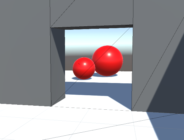
Here’s a video of the effect:
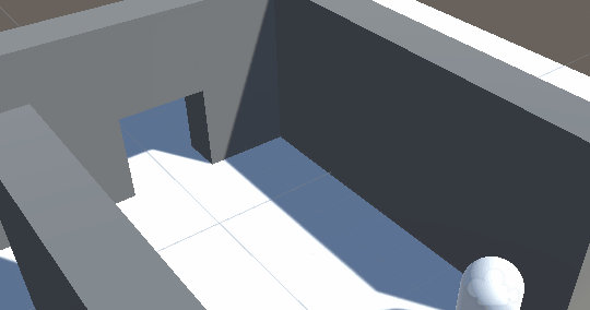
Each doorway has a hidden wall which becomes visible when you enter a trigger. At the same time, a texture is generated by a camera and is applied to the wall. Here’s what it looks like from another angle:
The effect can be broken down into two parts: generating the texture and applying it to the object.
Generating the texture
The effect must work regardless of what the player is looking at. If the object is only partially on screen or behind the player then using a section of the player’s view would be insufficient. This is resolved by creating a temporary second camera at the same position as the player camera but facing towards the object.
The camera’s field of view should be as small as possible while still containing the whole object. If the field of view was 60 degrees but the object was far in the distance, most of the texture would be wasted. Conversely, if the field of view was 60 degrees but the object was a wall right in front of the player, it might not fit in the texture. An appropriate field of view is found by iterating through the corners of the object’s bounding box to find the largest horizontal or vertical field of view that any of them require.
float maxAngle = 0;
Vector3 min = meshFilter.sharedMesh.bounds.min;
Vector3 max = meshFilter.sharedMesh.bounds.max;
// Iterate through each of the 8 corners of the bounding box
foreach (float bx in new float[] { min.x, max.x })
{
    foreach (float by in new float[] { min.y, max.y })
    {
        foreach (float bz in new float[] { min.z, max.z })
        {
            // Get the corner's position in camera space
            Vector3 cornerInCameraSpace = cam.transform.InverseTransformPoint(transform.TransformPoint(new Vector3(bx, by, bz)));
            // Find the horizontal and vertical angles between the camera's forward vector and the corner's position
            float horizontalAngle = Mathf.Abs(Mathf.Atan(cornerInCameraSpace.x / cornerInCameraSpace.z));
            float verticalAngle = Mathf.Abs(Mathf.Atan(cornerInCameraSpace.y / cornerInCameraSpace.z));
            // If either angle is greater than the stored value, replace it
            maxAngle = Mathf.Max(maxAngle, horizontalAngle, verticalAngle);
        }
    }
}
// Set the camera's field of view based on maxAngle. MaxAngle is in radians so must be converted to degrees. Maxangle also only represents the angle between forward and the edge of the view, but field of view is the angle between the top and bottom of the view, so it must be multiplied by two.
cam.fieldOfView = maxAngle * Mathf.Rad2Deg * 2;
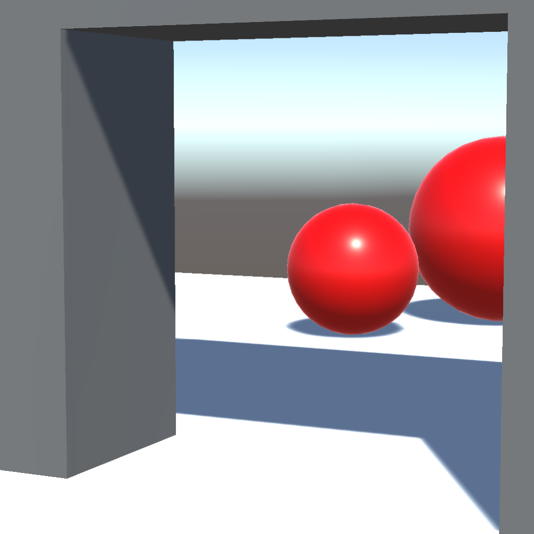
The camera then renders the image using a render texture as the target. I used a texture with 1024 x 1024 pixels. The texture it produces looks like this:
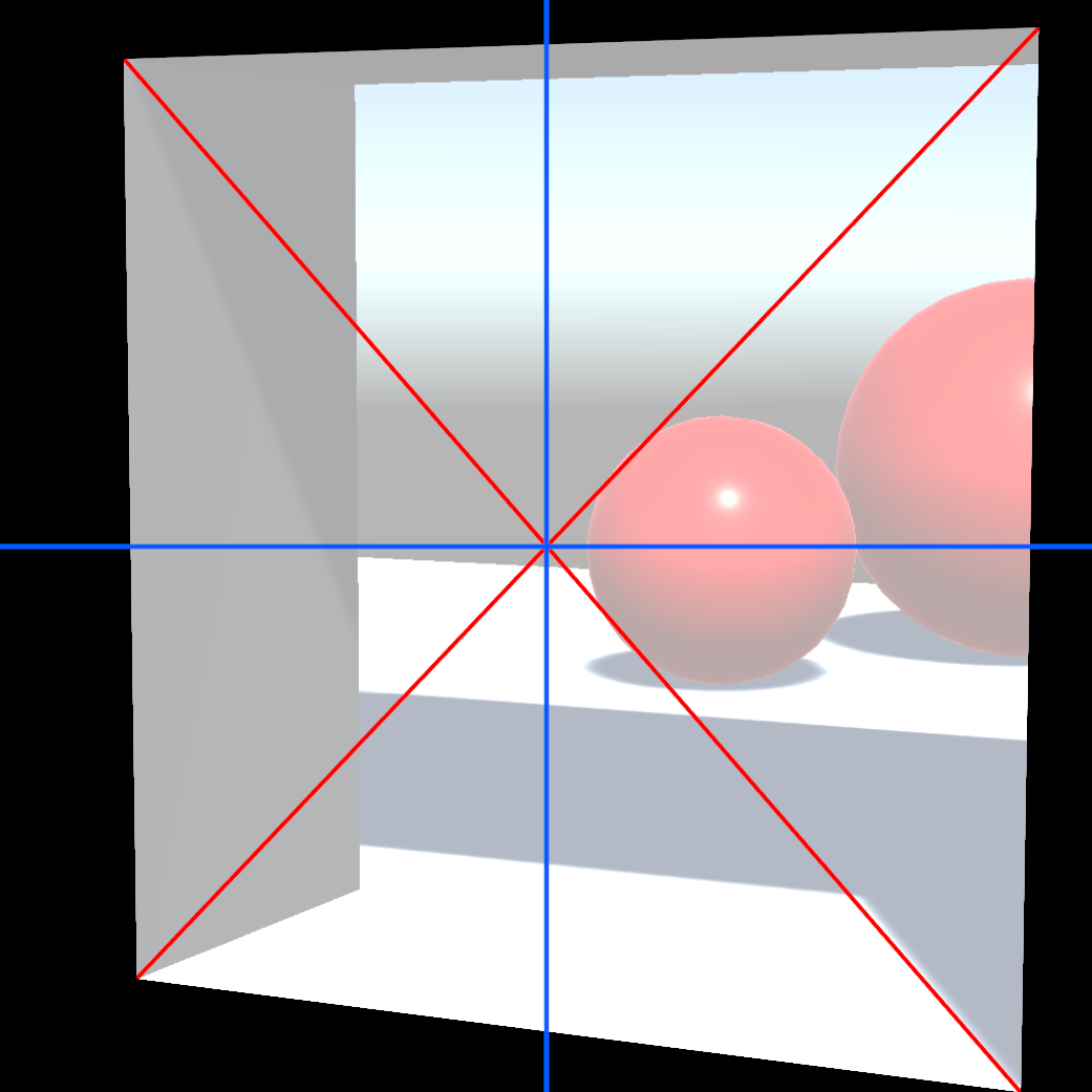
The following image shows the region of the texture that is occupied by the object’s bounding box. The centre of the bounding box (the intersection of the red lines) is at the centre of the texture (the intersection of the blue lines). The largest field of view required for any of the corners was the vertical field of view for the bottom right corner. As a result, the bottom right corner touches the bottom of the texture.
Applying the texture to the object
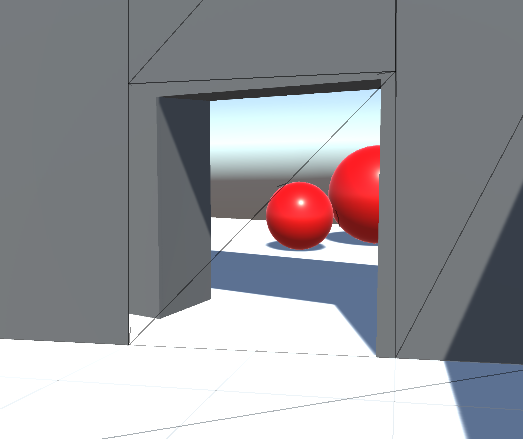
The next challenge is correctly mapping the texture onto the object. If we just applied the texture using the object’s UV coordinates it would look like this (I’ve enabled wireframe to make the shape clearer):
In order to correctly map the texture onto the object, the object’s vertex positions are projected into the screen space of the temporary camera. The projected positions are used to sample the texture.
Before the temporary camera is deleted, the matrix which converts world space to the camera’s clip space is calculated. This is found by multiplying the projection matrix by the world to camera matrix:
camMatrix = cam.projectionMatrix * cam.worldToCameraMatrix;
This matrix is passed to a shader along with the texture. In the vert shader the vertex position is projected first into world space then into the temporary camera’s clip space (clipPos is a float4 added to the v2f struct and _WorldToCam is the matrix that was passed to the shader).
// Project the vertex into world space
float3 worldPos = mul(unity_ObjectToWorld, v.vertex);
// Project the world space position into the temporary camera's clip space
o.clipPos = mul(_WorldToCam, float4(worldPos, 1));
In the frag shader the clip space position is converted into UV coordinates that are used to sample the texture:
// Get the UV coordinate
float2 uv = i.clipPos.xy / i.clipPos.w;
uv = (uv + float2(1, 1)) / 2; // Convert it from the range -1 to 1 to the range 0 to 1
// Sample the texture
fixed4 col = tex2D(_CamTex, uv);
The texture is now correctly mapped onto the object!
An alternative approach would be to project the texture just once and store it in another texture. This would be faster but it would be challenging to implement it in such a way that it could handle objects more complex than planes.